Welcome ... Product Categories ... What's New ... Sale Items ... Communications
E-Mail ... How to Order ... Order Form ... Catalog ... Legal Notices
|
|
||
|
HELP:
MP3 File Modifications
HELP: Flash Drive Formatting |
||
|
|
||
|
|
||
|
Digital
Sound Board Pro Series
1-6 Ch Record / Playback / Modules |
Sound
Board -VEGAS Series
1-8 Ch Record / Playback / Modules |
10
Ch MP3 Playback Board
10 Ch Stereo Audio Playback Control |
|
10
Channel MP3 - I/O System
10 Ch Sound, Video, Relay Control |
AutoTalk
- Control Board E2
Sound to Servo Motion Control |
10
Ch MP3 / Switched System
10 Ch Sound with 10 Switch Control |
|
Sound
Activated Relay Module
Relay Activated by Sound |
RF
Wireless 8Ch MP3 Player
Remote Audio Playback- 8 Ch |
10
Ch MP3 / Switch / Relay
10 Ch Switch & SS Relay Control |
|
Sound
to Solenoid / LED Driver
Solenoid Control SS Relay / Sound |
4
Ch Audio Mixer - Pro
4Ch Audio Input 1Ch Audio Output |
10
Watt Audio Amp Pro
Class D Audio 10Watt Amplifier |
|
4
Ch Audio Switcher with I/O
4 Ch In and Out Audio with Control |
Sound
Activated Delay Relay
Relay Activated by Sound |
63
Channel MP3 Player
63 Ch Stereo Sound SD Playback Board |
|
DMX - MP3
/WAV Controller
Audio Controller / Volume - Channels |
Sound
Activated Servo Driver
Sound Control of 1 Ch R/C Servo |
199-Ch
MP3 Timer Playback
Timer Random / Sequence Audio Play |
|
75 Watt
Audio Amplifier
Small Stereo Audio Amplifier |
2Ch Mic
- 1Ch MP3 Switcher
Mic / Audio Distribution Switcher |
4 Ch Audio
Basic Mixer Auto
4Ch Audio Input 1Ch Audio Output |
|
4"
Audio Speaker
4 - 8 Ohm Speakers |
512 Audio
Ch MP3 Player
MP3 Playback Board with features |
PRO Sound
Controller
1-8 Ch WAV file / Playback / Interface |
|
Mic to
AutoTalk Controller
Microphone Controlled AutoTalk |
Wizard-8
Sound / Relay
1-Ch Rec/Play/Servos/1 Relay Control |
RF Transmitters
& Receivers
RD Interface / Control Interface |
|
Audio
Cables
Audio Patch Cable -Y Adapter |
2 Ch Audio
Sound Switcher
2 Ch In / 2 Ch Out Stereo Control |
SB ProE
Ball Activation Switch
Unique switch interface module |
|
255-Ch MP3 Playback
System
255 Channel MP3 Sound Module |
Wizard-11 Motion /
Sound
4 Min Rec/Play AutoTalk & Controller |
Modular MP3 Playback
Board
10 Ch Stereo Sound Playback Board |
|
Mini Audio Amplifier
1- Watt Audio Amplifier Module |
Program 4 Ch Audio
Switch
1 Ch In / 4Ch Out Audio Control |
Wizard-5 Motion /
Sound
1-Ch Rec/Play/Servos/2 Relay Control |
|
SD Card / USB -SD
Reader
32 MB Memory, USB Card Reader |
15 Watt Stereo Audio
Amp
Mono & Stereo Audio Amplifiers |
Wireless Sound TX
and RX
Remote Sound Transmitter and Receiver |
|
1 Watt Audio Amplifier
Audio Amplifier- Mono & Stereo |
25 Watt Stereo Audio
Amp
Stereo Audio Amplifier |
1 Ch In to 8 Ch Out
Audio
1-8 Ch Audio Distribution Switcher |
|
Audio Signal to LED
Control
Sound Activated Power Switching |
Program 8 Ch Audio
Switch
1 Ch In / 8 Ch Out Audio Control |
Wizard-10 Sound /
1-8 Output
1-Ch 4 Min Rec/Play / Servo Controller |
|
Chipcorder and Servo
Driver
2-Ch ChipCorder and 4 Ch Servo Driver |
Manual On-Off MP3
Control
Instant ON / OFF Audio Playback |
Multi-Task MP3 Controller
Audio, Servo, Relay, PIR features |
|
Animate E2 Controller
1-63 MP3 Player / 4Ch Servo Control |
Wizard - 3 Board Controller
Programmable Servo-Relay-Sound |
Sound On Board Module
2-Ch ChipCorder Board |
|
Duo 63 x2 Channel
MP3
63 Ch x 2 Stereo Sound SD Board |
USB Memory Drives
Micro-Standard-Card Modules |
|
|
Other Controller
Boards
Wizard / Puppet / Other Modules |
SKE Products
Simon-Kaloi Engineering , LTD |
Audio
Switch Boards
Manual / Program/ Multiple Audio Ch |
|
Sound Product
Line Quick View
Sound / Video Product Part No. Catalog Sound Product 2009 Catalog / Quick Description PDF |
|
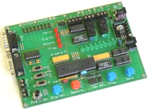
Digital Sound Board Pro,
and ProE Versions Record / Playback Module 1-6 Channels |
Hardware Description . | ||||||||||||||||||||||||
Board Size: 5" L x 2-1/8" W x 1-3/8" H Board is pre-assembled and tested. Board operates from 9 -Vdc @ 800 mA regulated power supply. Sound Board Pro Manual Application Examples 1 OPTIONAL CONNECTION Quick Wire Terminal Connector and 4" connector cable Example 1 of Connector to SB Pro Example 2 of Connector to SB Pro Example 3 of Connector to SB ProE Optional Switch / Adapter Module |
Recording and Playback Sound Board Newly Enhanced Versions Now with optional built in Random, Sequential, or Immediate sound On / Off playback features
The Digital Sound Board - ProE is a full featured mono digital
sound board with many unique features and applications.
|
||||||||||||||||||||||||
|
|||||||||||||||||||||||||
|
Sound Board - VEGAS
( Sound Board - 60 ) Record / Playback Module - 8 Channels |
Hardware
Description
.

|
||||||||||||||||||
Closeup View 1 Closeup View 2 Board Size: 3-1/2" L x 2-1/8" W x 1/2" H Board is pre-assembled and tested. Sound Board Quick Start Manual Sound Board Operation Manual Sound Board Applications - 1 Sound Board Applications - 2 Quick Wire Terminal Connectors Example of Connector to Sound Board YouTube Videos of Animatronic Characters using Sound Board Vegas |
Sound Board - VEGAS E Newly Enhanced Version
Record and playback 1 - 8 audio channels in manual switch,
or relay mode with individual channel selection or 8 channels
in random or sequence playback mode with a single switch, relay
or input signal, all with one unique digital memory sound chip
and controller.
|
||||||||||||||||||
|
|||||||||||||||||||
|
4 Ch Audio Switcher
with I/O Control |
Hardware Description | |||||||||
4 Ch Audio Switcher Switch sound to 4 different sets of speakers Click on images for a closeup view Board Size: 5.0" L x 3.5" W x 1.0" H Board is pre-assembled and tested. Sound Switcher Manual Sound and Animatronic Playback |
The 4 Ch Sound Switcher is designed to take a single sound
source and switch it to 1-4 different output channels under I/O
control (5 vdc signals) with 4 relays. The Sound Switcher can
be used with a CD player, Digital Sound Boards or any other audio
source signal
Switching Inputs:
4 Inputs for Switches, Sensors or
Contact Closures
Audio Input & Output:
Line Level Analog Audio
|
|||||||||
|
||||||||||
| 4 Ch Audio Mixer - PRO |
Hardware
Description
.......
|
||||||||||||
|
|
4 Input Channels to 1 Output Channel with Mix Capabilities The 4-Channel Audio Mixer Pro Active audio mixer allows you to take the audio ouput of up to four different audio output devices and mix them into one audio output channel. Take four audio inputs " Actively " mix them into one direct output audio channel, playing all four simultaneous audio outputs as one. On-board mix potentiometers with knobs allows for complete volume customization for each input audio channel.
Example: There are four audio devices being triggered by separate
sources, play tracks in different lengths of time, etc... but
you want to use only one set of speakers in the project. Use
the active mixer to take the individual outputs of the four individual
audio devices and mix them together into the one pair of speakers.
On-board knobs allow you to adjust the audio level for each individual
input audio device level
Speakers / audio amplifier, audio cables, power supply, sound playback system, switching input device not included. |
||||||||||||
|
|||||||||||||
| 4 Ch Audio Basic Mixer - Auto |
Hardware
Description
.......
|
|||||||||
|
|
The 4-Channel Audio Basic Mixer passive audio mixer allows
you to take the audio ouput of up to four different devices and
automatically merge them into one audio output.
|
|||||||||
|
||||||||||
|
Programmable 4 Channel
Audio / Stereo Switcher |
Hardware Description | |||||||||
Switch Stereo Sound to 4 different sets of speakers Board Size: 4-3/4 L x 5" W x 1" H Board is pre-assembled and tested. |
Board will take a stereo sound input and distribute it to
any of 4 output channels. The output channel that the sound will
come out of is programmed by the user. Multiple Channels can
be selected together. A program can last up to 15 minutes. There
is a Loop Switch that will cause the program to repeat after
a delay that is set by an on-board potentiometer. The board can
be triggered by pressing the Play Button, a dry contact closure
at the Remote Trigger Terminal or by an optional PIR sensor (not
provided). Also, the board can run in Random Mode where the outputs
are randomly selected (one at a time) and will stay selected
for an amount of time entered by the Delay Pot. When playback
is initiated, a 50 mS dry contact closure will occur at the Synch
Out Terminal. This can be used to trigger another device (like
a sound board) to start simultaneously.
|
|||||||||
|
||||||||||
|
Programmable 8 Channel
Audio / Stereo Switcher |
Hardware Description | |||||||||
Switch Stereo Sound to 8 different sets of speakers Board Size: 7" L x 5" W x 1" H Board is pre-assembled and tested. |
Board will take a stereo sound input and distribute it to
any of 8 output channels. The output channel that the sound will
come out of is programmed by the user. Multiple Channels can
be selected together. A program can last up to 15 minutes. There
is a Loop Switch that will cause the program to repeat after
a delay that is set by an on-board potentiometer. The board can
be triggered by pressing the Play Button, a dry contact closure
at the Remote Trigger Terminal or by an optional PIR sensor (not
provided). Also, the board can run in Random Mode where the outputs
are randomly selected (one at a time) and will stay selected
for an amount of time entered by the Delay Pot. When playback
is initiated, a 50 mS dry contact closure will occur at the Synch
Out Terminal. This can be used to trigger another device (like
a sound board) to start simultaneously.
|
|||||||||
|
||||||||||
|
2 Channel Audio - Stereo
In / Out Sound Switcher |
Hardware Description | |||||||||||||||
Board Size Approx: 4" L x 2-1/2" W x 1/2" H 1/8" miniplug audio jack Instruction Manual |
Newly Enhanced Version (Optional Remote Wireless or Ribbon and Switch Control)
This board will allow the user to select between 2 stereo
sound inputs and 2 stereo outputs and switch them in various
configurations.
Application:
Control Board can connect a Microphone
and Amp , MP3 player, AutoTalk Board and Audio - Amp / Speaker
together and allow user to talk through AutoTalk Board or have
MP3 playback through AutoTalk, while also going to a Amp / Speaker
system output.
|
|||||||||||||||
|
||||||||||||||||
|
1 Ch In - 8 Ch Out Audio
Stereo Sound Switcher |
Hardware Description | |||||||||
Board Size Approx: 6" L x 2-3/4" W x 5/8" H Instruction Manual |
This unique board is designed to allow you to distribute a
stereo sound from a single input to one of 8 outputs in sequence,
random or sequence automatic when a trigger event (dry contact
closure or tactile switch press) is activated.
|
|||||||||
|
||||||||||
|
2 Ch Microphone - 1 Ch MP3
Audio Sound Switcher |
Hardware Description | ||||||
Main Board Size Approx: 6-3/8" L x 3-1/8" W x 5/8" H Remote Switch Board Size Approx: 3" L x 1-1/2" W x 1" H |
This board will allow the user to select between 2 microphone
inputs and one audio input to be routed to a stereo output jack.
|
||||||
|
|||||||
|
Wireless Sound
Transmitter and Receiver Modules |
Hardware Description | ||||||
Board Size Approx: 4" L x 2-5/8" W x 5/8" H |
Audio Transmitter and Receiver Modules
|
||||||
Custom Order, Please Contact Blue Point Engineering for Details |
|||||||
|
Sound Activated Solid State
Relay Driver Board ( Solenoid / LED Driver) |
Hardware Description | ||||||
Board Size Approx: 3-1/4" L x 2-3/8" W x 3/4" H Relay = 1 Amp @ 60 VDC Instruction Manual Application Examples: Pneumatic- Mouth Mechanism Water Valve- Dancing Fountain LED's - Dancing Lights DC Motor Driver- "Talking Fish" |
Board accepts audio input from any non-amplified sound source
(computer, CD player, or Digital Sound Board) and activates a
Solid State Relay ON and OFF in sync with the incoming audio
signal. The on-board 1 Amp Solid State Relay can be connected
to any device using (3-60 Vdc @ 1 Amp power). Common application
include driving a pneumatic solenoid valve, water valve to sound
or operating large bank of LED's -DC lighting to the incoming
sound.
|
||||||
|
|||||||
|
Professional Sound
Control System Ready to Operate Audio Playback System |
Hardware
Description
.........
|
||||||||||||||||||||||||
|
Optional
|
Feature packed, proven quality and reliability, the Pro Sound
Card is a digital audio repeater that can be used for interactive
displays, standalone music, message announcement, concert audio,
home theater audio, Animatronic shows or anywhere quality audio
is needed for your application. The Pro Sound Card is simple
to operate and setup, you simply record the WAV files on your
PC, and name the WAV files how you want them to play. You next
copy the WAV files to a Compact Flash card, connect speaker(s),
and plug in the Pro Sound Card using the included wall transformer.
Audio is played out via the built in High Power Stereo amplifier,
or you can connect it to your own amplifier using the line-level
out jacks.
The Pro Sound Card's 44kHz 16 Bit stereo CD/DVD quality audio and built in digital stereo amplifier will astound you. Connect a set of quality speakers and you will not believe the fidelity and power of what you hear. The built in Class D amplifier generates unbelievable audio power with no heat! It's digital right to the speakers! You can record your audio files using the sound recorder software included with your computer, our use one of the many audio editing software packages that are free on the internet. Using an audio editing software allows you to add effects, fades, noise, tones, touch tones, silence, background music and more, that will make your audio WAV files sound like they were done by a pro. Volume may be remotely adjusted by connecting momentary push button switches to the provided pin header connector located on the main PCB , or the on-board buttons can be used to control sound levels of the Pro Sound Card.
* Operates on 12 - 15VDC. - 0.5 Amp
NOTE: Maximum file size is 4 gig 2- Gig FLASH Card, Wall power supply, Two Speakers, 8 remote wired switches and hookup wire included. Switch Harness Eight 1.4" Diameter Black push buttons wired on 10' of 22 gauge 12 conductor wire. Each switch is labeled 1 - 8. Switches are grouped in to four groups of two switches. Each group has 16" of wire to them, so each group can be mounted 30"-32" from the furthest group. The electrical part of the switch easily snaps off the bottom of the of the mounted portion of the switch, so that it can be installed without removing the wiring. The other end of the 22 gauge 12 conductor cable has a 10 Pin connector on it for plugging into an IO expansion module on the Sound Board Controller. |
||||||||||||||||||||||||
|
|||||||||||||||||||||||||
|
AutoTalk Controller - E2
Sound to Servo Motion Control |
Hardware
Description
.... .
|
|||||||||||||||
Board Size: 2-3/4" L x 2-1/2" W Board is pre-assembled and tested. AutoTalk Instruction Manual Using a Digital Servo or Large Servo with the AutoTalk Application Note Other Animatronic Controllers that work with the AutoTalk Controller Board AutoTalk Comparison -vs- Others YouTube Videos of Animatronic Characters using AutoTalk AutoTalk Optional Accessories |
(Recognized as one of the best Audio to Sound Converter Available)
The AutoTalk -E2 board is similar in function with all the
exact features of the original AutoTalk board developed several
years ago for professional animatronic clients, in that it moves
an R/C type servo in response to either an audio input signal
from any standard CD player, tape recorder, sound source, but
now has jumper setting for greater sensitivity in using the board
from a sound source with low signal input, such as found on a
digital sound chips or direct connected mic amplifier and dynamic
microphone setup. The board has an on-board voltage regulator
for using a variety of voltage sources including the use of a
battery for remote applications, a quick connector for connecting
power, LED power status indicator and enhanced output to operate
a standard R/C servo with greater response. The controller includes
the function to set both the servo end travel points, an important
feature when working with various mouth jaw sizes, the servo
arm direction of travel can also be quickly changed by an on-board
jumper and the sensitivity of the audio input signal through
the improved on-board gain control have also been enhanced for
greater response.
|
|||||||||||||||
|
||||||||||||||||
|
Wireless RF 8 Ch Audio
MP3 Playback Controller |
Hardware Description | ||||||
|
Wireless 8 Channel MP3 Audio Playback controller
|
||||||
|
|||||||
|
Wizard - 8 Board
On-board Sound and Programmable Relay |
Hardware Description | ||||||||||||
Board Size: 3-1/2" L x 3-3/4" W x 1/2" H Board is pre-assembled and tested. Wizard - 8 Document Application Note |
The Wizard - 8 board provides a single channel, user programmable
5 - minute
digital output (
relay
) combined with
a digital
4 - minute
duration user record IC
sound
chip
. The supplied 4 - minute ISD sound chip has great frequency
response up to 3.4 KHz and a audio sample rate of 8.0 KHz. Audio
can be re-recorded up to 100,000 times and can be stored up to
100 years.
|
||||||||||||
|
|||||||||||||
|
Wizard - 5 Board
Animatronics Controller |
|
|||||||||
|
Servos, Digital, Sound, and Sound
|
Servo / Sound / Digital / Sound to motion all on one board
The
Wizard - 5 Board
will record and playback up to
5
minutes
of action for up to
2 servo
s and
2 digital outputs
. It also incorporates a
4-minute audio
recording and playback sound chip
with the ability to control
one servo channel either from recorded moves or from an audio
signal, direct or from on-board sound chip.
|
|||||||||
|
||||||||||
|
Wizard - 11 Board
On-board Servos, Digital Sound, AutoTalk, 6-Servos, 2-Relays |
Hardware Description | ||||||||||||||||||
|
Ultimate Animatronic Board
|
AutoTalk Controller
The
Wizard - 11 Board
will record and playback up to
6
minutes
of action for up to
6 servo
s and
2 digital outputs
(on-board relays). It also incorporates
a
4-minute audio recording and playback sound chip
with
the ability to control one servo channel (
AutoTalk
)
either from recorded moves or from an audio signal, direct or
from on-board sound chip.
|
||||||||||||||||||
|
|||||||||||||||||||
|
Wizard - 10 Sound with 1- 8
Multiple Channel Outputs |
Hardware Description | ||||||||||||||||||
|
The other 8 banks of pin-sets along the back edge are for selecting which sound track goes to which output- jack matrix. ( remote amp and speaker ) Pin-set 1 (on the extreme left) relates to sound track 1- if you want sound track 1 to play-back through outputs 2, 6 and 8 you would put a jumper over pins 2, 6 and 8 on pin-set 1.
If you want to play sound -track 2 through outputs
1,3 and 5 then you would put jumpers over pins 1, 3 and 5 on
pin-set 2 etc.
|
Programmable board will switch 8 different digital audio recorded
signals to 1-8 different output channels.
There is 1 audio jack input for recording 8 different sounds into the Digital sound chip directly by an audio source and 8 on board line output channels jacks to remote amps and speakers setups. There is the standard record/playback mode jumper selection along with led indicators. Board can even be set to play random or sequence sound playback when triggered You can adjust the play-back output select jumpers at any time- they are read just before starting any new play-back.
When the audio is combined with any of the Wizard Relay boards,
the system becomes an automated audio sound effects and switcher
system.
|
||||||||||||||||||
|
|||||||||||||||||||
|
DMX - MP3 Controller
( VMusic2 Interface Board ) |
Hardware
Description
........ ....
|
||||||||||||||||||
Click on Image for Additional View 
MP3 Board Setup Instructions Board Programming Guide Quick Operating Overview Sample TEST Audio Files 1-32 Test Procedures for MP3 |
( VMusic2 Interface Board) Custom interface board allows you to add the VMusic2 MP3 Player to your DMX project or display. Requires either 3 or 4 DMX channels and the control protocol allows easy use with a standard DMX (slider) desk.
Playback, Stop, Pause and Resume functions
NOTE: due to the restrictions of the VMusic2 Player , the volume levels cannot be updated more than once every 0.5 seconds
Connections
Base Address Selection
Indicators
(Audio cables, USB Drive, DMX Interface, Audio files, Speakers,
Amp, Power Supply not included)
|
||||||||||||||||||
|
|||||||||||||||||||
|
10 Channel - MP3
Audio Playback Controller Sequence / Random Playback Options |
Hardware Description | |||||||||||||||||||||
|
Click Image for a Close-up View
Optional MP3 Bracket / Stand
|
10 Channel Audio Playback / Sequence / Random Newly Enhanced Version
Here is a very simple audio controller that when triggered
by pressing the single on-board button or by dry contact closure
at the trigger terminal, will cause the player to play back 1
to 10 MP3 files that are stored on a USB flash device (USB pen
drive not included). These MP3 files can be of any size up to
the capacity of the USB flash device. You can have any number
of files up to 10 on the flash device. Unique setup allows USB-MP3
Module to be mounted in box, cabinet for easy access to USB and
Audio Jack ports. Power Requirements - 9 Vdc @ 0.5 Amp
Remote Sensor boards
can be
added to trigger the audio playback board automatically, or manual
switch can be used to start playback
|
|||||||||||||||||||||
|
||||||||||||||||||||||
|
63 Channel - MP3
Audio Playback Controller |
Hardware Description | ||||||||||||
Click on images for a Closeup View 
Board Size: 2" Wide x 4" Long x 1-1/2" High 32MB - SD Card Included Board Power Supply Required 9 VDC @ 0.5 Amp regulated |
Here is an audio controller that when triggered by pressing
the single on-board button or by dry contact closure at the trigger
terminal, will cause the player to play back 1 to 63 MP3 quality
files that are stored on a small SD Card. These MP3 files can
be of any size up to the capacity of the SD memory card, You
can have any number of files from 1 to 63 on the SD card. Board
operates from 9 Vdc @ 0.5 Amp regulated VDC Power Supply. 1/8"
miniplug audio output jack.
Remote Sensor boards
can be
added to trigger the audio playback board automatically, or manual
switch, remote hand held RF modules, external relays can be used
to start playback
|
||||||||||||
|
|||||||||||||
|
Duo 63 Channel - MP3
Audio x2 Playback Controller |
Hardware Description | ||||||||||||
|
|
This very unique audio controller has two 63 channel MP3 playback
controlled players on a single board. Each MP3 player can be
independently triggered by pressing the single on-board button
or by dry contact closure at the trigger terminal for each MP3
module and will cause each player to play back 1 to 63 MP3 quality
files that are stored on a small SD Cards. These MP3 files can
be of any size up to the capacity of the SD memory cards, You
can have any number of files from 1 to 63 on each SD cards. Board
operates from 9 Vdc @ 0.5 Amp regulated VDC Power Supply. 1/8"
miniplug audio output jacks.
2x- 32MB - SD Cards Included
|
||||||||||||
|
|||||||||||||
|
199 Channel - MP3
Audio Playback with AutoTimer |
Hardware Description | ||||||||||||
Board Size: 3-1/8" Wide x 3" Long x 1-1/2" High 32MB - SD Card Included Board Power Supply Required 9 VDC @ 0.5 Amp regulated |
with user set Automated Time Trigger
This is an audio controller that has an on board timer that
can be set for 9 various times to automatically play back 1 to
199 MP3 files that are stored on a small SD Card or triggerd
traditional by external switch or dry contact closure, relay
boards. These MP3 files can be of any size up to the capacity
of the SD memory card, You can have any number of files from
1 to 199 on the SD card.
This MP3 controller can be used in a prop, animatronics, puppets,
information display exhibits, museums, zoos, as public information
boards and other areas, anywhere where you might need an audio
file to be played back based on an automated time trigger.
|
||||||||||||
|
|||||||||||||
|
MP3 Audio Playback with
AutoTimer and 2 Channel Solid State Relays 1 - 199 Audio File Playback |
Hardware Description | ||||||||||||
Board Size: 4 Wide x 3-1/4" Long x 1-1/2" High Solid State Relays - 2 Amp each 32MB - SD Card Included Board Power Supply Required 9 VDC @ 0.5 Amp regulated |
with user set Automated Time Trigger and 2 Channel Solid State Relays
This is an audio controller that has an on board external
trigger input or can be activated by on board timer that can
be set for 9 various times to automatically play back 1 to 199
MP3 files that are stored on a small SD Card and also activate
two (2) Solid State relays for 200 mSec ON closure/pulse when
triggered.
|
||||||||||||
|
|||||||||||||
|
1 Channel - MP3 Playback
Board with Manual Instant ON and OFF Audio Control |
Hardware Description | ||||||||||||
Board Size: 2-3/4" Wide 3-1/8" Long 1-1/2" High 32MB - SD Card Included Board Power Supply Required 9 VDC @ 0.5 Amp regulated |
This unique MP3 audio controller has the ability to immediately stop and re-start a single channel audio play back by manual control from a remote connected momentary switch. The MP3 file can be of any size up to the capacity of the SD memory card.
This MP3 controller can be used in a prop, or working railroad
model, (Train Whistle) anywhere a sound is need to be immediately
stopped and re- started manually at any time by a remote connected
switch.
|
||||||||||||
|
|||||||||||||
|
SD Memory Card
MP3- Audio Player USB - SD Memory Card Reader CF Type 1 Memory Card |
Hardware Description | |||||||||||||||||||||
SD Memory Card 32-MB
|
USB - SD Memory Card Reader
MP3- Audio Memory Card
SD card to USB Adapter
NOTE: USB Reader may vary in style from images shown
SanDisk - Standard USB Flash Drive
SanDisk - Micro USB Flash Drive
|
|||||||||||||||||||||
|
||||||||||||||||||||||
|
10-Ch MP3 Playback Board
with Remote 10-Ch Switch Board Sequence / Random / Ch Selection |
Hardware Description | |||||||||||||||||||||
MP3 Player Board, VMusic2 Module and 10 Channel Remote Switch Input Board 
|
Remote 10 Ch Switch Selection Board Newly Enhanced Version
An MP3 Stereo Audio Controller, that when triggered by optional
remote relays or manual switches connected to the remote switch
input board will cause the player to play back 1 to 10 MP3 files
that are stored on a USB flash device (USB flash drive not included).
These MP3 files can be of any size up to the capacity of the
USB flash device. You can have any number of files up to 10 on
the flash device. Board operates from 9 VDC @ 0.5 Amp Power Supply.
|
|||||||||||||||||||||
|
||||||||||||||||||||||
|
10-Ch MP3 PRO - Modular System
Sequence / Random / Ch Selection / IO Boards 10-Ch MP3 Audio Playback Board + 10-Ch Switch Board + 10-Ch Audio Switch Board + 5/10-Ch Solid State Relay Control Board |
Hardware Description | |||||||||||||||||||||||||||||||||
|
(A)
|
Newly Enhanced Version This advanced expandable MP3 stereo audio10-Channel full function control system, allows the designer the option to use the base MP3 stereo board stand alone or to add and mix different output function boards for specific applications as needed. Audio, Video and Solid State Relays 10-channel boards can be connected to the main MP3 playback board and will switch on and off as each audio channel is selected and played back from the base playback module. Any remote board combinations can be connected to the main Audio Playback board. Board operates from 9 VDC @ 0.5 Amp Power Supply
When the main MP3 audio control board is triggered by activating
the remote channel 1-10 switch board or by dry contact closure
(Relay), this will cause the player board to playback 1 to 10
MP3 files selected that are stored on a USB flash device and
turn on each added remote control Video, Sound, Solid State Relay
board attached by a ribbon connector. Each remote board will
also activate a channel corresponding to the main audio channel
selected 1-10
The designer can purchase the basic MP3 Playback board and
remote switch board stand alone or add as many additional remote
boards as needed (Audio, Video, SS Relay Boards)
( Power supply, speakers, remote amp, switches, audio connection
cables, USB Flash drive not included )
Note: SanDisk USB Drive Recommended |
|||||||||||||||||||||||||||||||||
|
||||||||||||||||||||||||||||||||||
|
10-Ch MP3 Audio Playback Board
10-Ch Switch Selection Board 5/10-Ch Solid State Relay Control Board Sequence / Random / Ch Selection / Relay Boards |
Hardware Description | ||||||||||||||||||||||||||||||||||||
|
MP3 Stereo Playback Module / Relay System
|
Remote 10 Ch Switch Selection Board Optional 5/10 Solid State Relay Boards Newly Enhanced Version
Advanced full function MP3 audio control board, when triggered
by activating the remote channel 1-10 input switches or by dry
contact closure (Relay), will cause the player to play back 1
to 10 MP3 files that are stored on a USB flash device and turn
on a remote
(B. C)
Solid State Relay board corresponding
to the sound channel activated 1-10. Board operates from 9 VDC
@ 0.5 Amp Power Supply
Main Sound Control Board can be operated without attached
solid state relays if needed. A total of 10 Relays can be added
to main sound control board.
Remote Sensor boards can be added to trigger the audio playback board automatically, or manual switches can be used to playback channels.
Several board configuration setup options available
|
||||||||||||||||||||||||||||||||||||
|
|||||||||||||||||||||||||||||||||||||
|
255 Channel - MP3
Audio Playback Controller |
Hardware Description | ||||||||||||||||||

Main Control Board 3-1/8" Long 2-3/4" Wide 1/2" High USB-MP3 Module 2-3/4" Long 1-3/4" Wide 7/8" High 1/8" miniplug audio output jack Board Power Supply Required 9 VDC @ 0.5 Amp regulated Note: SanDisk USB Drive Recommended HELP: MP3 File Modifications HELP: Flash Drive Formatting |
Newly Enhanced with New Features
Here is a very simple audio controller that when triggered
by pressing the single on-board button or by dry contact closure
at the trigger terminal, will cause the player to play back 1
to 255 MP3 files that are stored on a USB flash device (USB pen
drive not included). These MP3 files can be of any size up to
the capacity of the USB flash device. You can have any number
of files up to 255 on the flash device. Unique setup allows USB-MP3
Module to be mounted in box, cabinet for easy access to USB and
Audio Jack ports. Board operates from 9 VDC @ 0.5 Amp Power Supply
Remote Sensor boards
can be
added to trigger the audio playback board automatically, or manual
switch can be used to start playback
|
||||||||||||||||||
|
|||||||||||||||||||
|
512 Channel - MP3
Audio Playback Controller with Relay and PIR Sensor |
Hardware Description | |||||||||||||||||||||
Main Control Board 4-1/8" Long 3-1/8" Wide 7/8" High USB-MP3 Module 2-3/4" Long 1-3/4" Wide 7/8" High Board Power Supply Required 9 VDC @ 0.5 Amp regulated HELP: MP3 File Modifications HELP: Flash Drive Formatting |
Very unique controller that uses VMusic2 MP3 Player and microprocessor
controller to playback 512 audio files, with on-board PIR Sensor
and Relay design. The controller, when triggered by pressing
the on-board Play button or by dry contact closure at the trigger
terminal, will cause the player to play back one of up to 512
MP3 files that are stored on a USB flash device (i.e., USB pen
drive - not included). These MP3 files can be of any size up
to the capacity of the USB flash device. You can have any number
of files up to 512 total files on the flash device. An on board
5Amp relay that will activate and stay on while the current audio
file is playing. is available. There is an optional PIR sensor
connector and control circuit also built on board if you want
playback automated with sense and play features.
|
|||||||||||||||||||||
|
||||||||||||||||||||||
|
Multi-Task MP3- 512 Ch Player
with R/C Servo AutoTalk, Relay PIR Features |
Hardware Description | |||||||||||||||
|
This unique board uses a VMusic2 MP3 module Player and several PIC microprocessors to playback MP3 Audio, control an R/C servo with sound motion (AutoTalk), activate a 5 Amp mechanical Relay through on-board manually, remote trigger or by PIR Sensor. The controller, when triggered by pressing the on-board Play button, by dry contact closure at the trigger terminal or optional PIR sensor will cause the player to play back one of up to 512 MP3 files that are stored on a USB flash device and use the volume of the sound played to control the movement of a R/C servo. The MP3 files can be of any size up to the capacity of the USB flash device. You can have any number of files up to 512 total files on the flash device. There are 2 modes of file playback provided Sequential and Random. The mode is set using the small slide switch located near the connector for the player module or by providing a dry contact closure at the Remote R/S Selection Terminal Block. When the contact is closed, the board will be in Random mode. In Sequential Mode, the player will play the files back sequentially from file001.mp3 to file512.mp3 (or whatever your last file is), one file at a time each time the board is triggered. There is a Playback Delay Potentiometer that will allow you to prevent the board from being re-triggered for up to 5 minutes after the audio file has played. If the potentiometer is set to zero, the board can be retriggered immediately after the previous file has ended. If the pot is set at greater than zero, a yellow status LED will flash once/second during the wait period. After it has played the last file, it will go back to file001.mp3 and start over. If the board is powered off, it will remember that last file played and when powered on again, will play the next file. In Random Mode, it will pick one of the files to play back at random. It will pick a new file each time the board is triggered. A 5 Amp relay will activate and stay on while the current audio file is playing. The audio from the VMUSIC2 module is routed to a stereo audio jack on the board. When a file is playing, audio will be available there as well as from the front of the MP3 module. Audio from these outputs can be sent to an optional audio amplifier and out to speakers.
Board has a terminal block for a remote power switch., Wire
Terminal Strips, LED Status LEDs and on-board option to set Servo
Travel limits
|
|||||||||||||||
Custom Order, Please Contact Blue Point Engineering for Details |
||||||||||||||||
|
Wizard - 3 Board
8 - Servo / Digital Controller |
|
|||||||||||||||
Board Size: 6-5/8" L x 4-1/2" W Wizard - 3 Board is pre-assembled and tested. Controller has 7-bit Resolution. Note: Regulated 9 Vdc @ 2 Amp and Regulated 5 Vdc @ 2 Amp power supplies recommended Example Setup Wizard-3 Manual / Overview |
The
Wizard 3 board
will record and playback up to 4
separate tracks for up to 8 R/C type servos channels and 8 digital
channels. The maximum recording time per track is 3 minutes for
multiple track operation or 6 minutes for single track operation.
The card incorporates features such as looping action with variable
delay between loops, auto start-up on power up, a connection
interface for a PIR, remote switch or pressure pad to initiate
playback and the ability to daisy-chain several
NOTE:
Controller requires 2 Power Supplies(1-9VDC and
1-5 or 6VDC)
( 9 Vdc @ 2 Amp and 5-6 Vdc @ 2 Amp power supplies recommended
)
|
|||||||||||||||
|
||||||||||||||||
|
Sound Activated Relay Module
(10 Amp Mechanical Relay) |
Hardware Description | ||||||
|
|
(10 Amp Mechanical Relay)
Board accepts audio input from any non-amplified sound source
(computer, CD player, or Digital Sound Board) and when the volume
reaches a certain level, it activates an on board 10 Amp relay.
The relay can be used to switch another device on and off in
sync with the volume of the input. There is an on-board potentiometer
that is used to adjust the sensitivity to the incoming sound.
The board has a 1/8" phono jacks for input that can be switched
as a left or right audio input signal. An on board LED indicates
when the 10 Amp relay is activated. Relay has NO, Com, NC wire
terminal block contacts (form C relay). Board operates from 12
VDC power supply.
|
||||||
|
|||||||
| Sound Activated Delay Relay | Hardware Description | ||||||
Board Size Approx: 3-7/8" L x 2-5/8" W x 7/8" H Instruction Overview Resistor Time Chart |
(10 Amp Mechanical Relay) Board accepts audio input from any non-amplified sound source (computer, CD player, or Digital Sound Board) and when the volume reaches a certain level, it activates the on-board delay timer relay circuit on. The relay can be set to switch off after a delay time period.
Sound Input:
There is an on-board potentiometer that
is used to adjust the sensitivity to the incoming sound. The
board has a 1/8" phono jacks for input that can be switched
as a left or right audio input signal. An on board LED indicates
when the relay circuit is activated.
|
||||||
|
|||||||
|
Sound Activated
R/C Servo Driver Board |
Hardware Description | |||||||||
Board Size: 4-1/8" L x 3-1/8" W x 1/2" H 1/8" miniplug audio output jack |
Control Board operates a R/C servo motor in response to sound
from a non-amplified sound source (computer, CD player, etc.)
|
|||||||||
|
||||||||||
|
Animate E2 Controller
MP3 Sound and 4 Ch Servo Control |
Hardware Description | ||||||||||||
|
|
This special board was designed to allow the recording and
playback of up to 10 minutes of 4 servo outputs and 1 to 63 channels
of audio MP3 playback.
The Animate E2 board incorporates many features such as looping playback servo motion with variable delay between loops. On board connector for remote activation switching such as a PIR sensor, contact switch or mat pressure pad to initiate servo playback and on-board sound output.
No complex programming is required. Programming is easily
done, with a set of push button keys and control potentiometer
built onto the board. Power Switch ON / OFF. Connection pins
on-board for servos, wire terminal block fo easy hookups.
Also on board is a audio controller that when the board is
triggered by pressing the single on-board button or by dry contact
closure at the trigger terminal, will cause the player to play
back 1 to 63 MP3 files that are stored on a small SD Card and
playback the recorded 4 servo channels These MP3 files can be
of any size up to the capacity of the SD memory card, You can
have any number of files up to 63 on the SD card.
|
||||||||||||
|
|||||||||||||
|
Audio Signal to LED
Controller |
Hardware Description | ||||||||||||
Board Size Approx:: 2" L x 1-1/4" W x 1-3/4" H |
Controller takes audio signal and outputs a user selected
|
||||||||||||
|
|||||||||||||
|
2- Channel Chipcorder
Audio Record / Playback Module |
Hardware Description | |||||||||
Board Size: 4-1/4" L x 2-3/4" W x 3/4" H |
Audio Record and Playback Module
Audio record and playback board based on the ISD4002 sound
chip that allows you to record 1 or 2 audio clips, into the On-Board
ISD chip, which can be 2 channels, 60 seconds each channel, or
1 channel for 120 seconds of audio recording
|
|||||||||
|
||||||||||
|
2- Channel Chipcorder and
4- Channel R/C Servo Driver |
Hardware Description | |||||||||
Board Size: 5-5/8" L x 5-1/4" W x 1/2" H |
4-Channel R/C Servo Driver Board
This board was designed to allow the recording and playback
of up to 10 minutes of 4 servo routines and up to 4 minutes of
audio.
Audio Channel 1 will playback with the 4 servo channels when
board is triggered for playback. Audio Channel 1 and 2 can be
played at any time and are independent of the 4 servo channels
.
Audio Input jack for direct sound into ISD sound chip and
Audio output jack for connection to sound amp and speaker.
Requires two power supplies, Servo Power, on Board Electronics
|
|||||||||
|
||||||||||
|
Dynamic Mic to AutoTalk
Controller Board Interface |
Hardware
Description.
.......
|
||||||||||||
Board Size Approx: 2-3/8" L x 1-1/2" W x 1/2" H Mic Board Instructional Manual AutoTalk Instruction Manual |
Connect this unique board to a Dynamic Microphone, an AutoTalk
controller board and you have a module that will control the
AutoTalk Servo movement as you talk through the microphone.
|
||||||||||||
|
|||||||||||||
| 10 Watt AUDIO AMP - PRO |
Hardware
Description
.......
|
||||||||||||||||||
Small Board Size: 31/2" L x 2" W x 1-1/4" H Board is pre-assembled and tested. Application Notes Setup Examples |
10 Watt Class D Stereo Audio Amplifier.
Power your own speakers directly with this very efficient
stereo power amplifier. All connections are made using screw
closure terminal strips to allow for simple and direct wiring
of speakers and supplying power. Volume is adjustable using the
handy on-board potentiometer with turn knob to allow for precise
control of volume. The audio source input is supplied simply
by taking an audio patch cable and connecting the AMP Pro to
a playback device such as any of the Blue Point Engineering MP3
Playback Control Boards.
|
||||||||||||||||||
|
|||||||||||||||||||
|
Mini Audio Amp Module
1 - Watt- Mono Output |
Hardware Description | |||||||||
Click on image for a view of system setup using Mini Audio Amplifier. Amplifier Size Approx: 3.375" L x 3.125" W x 1.75" H |
Small Mini Audio Amplifier Module.
High-gain IC circuit
|
|||||||||
|
||||||||||
|
Audio Amplifier Board
1 Watt- Mono Output 1 Watt- Stereo Output |
Hardware Description | |||||||||||||||
|
|
1-Watt Mon Audio Amplifier board
1/8" miniplug audio output jack
1-Watt Stereo Audio Amplifier board
|
|||||||||||||||
|
||||||||||||||||
|
Audio Amplifier Board
15 Watt - Stereo |
Hardware Description | ||||||||||||||||||||||||
|
|
NOTE: Best All-Around Amp Board
15 Watt Digital Audio Amplifier, designed around the Tripath
TA-2024 IC, 15 Watt continuous average two-channel Class-T digital
audio power amplifier. Class-T amplifiers offer both the audio
fidelity of Class-AB amplifier and the power efficiency and cool
operating of a Class-D amplifier.
Features Tripath TA-2024 IC
|
||||||||||||||||||||||||
|
|||||||||||||||||||||||||
|
Audio Amplifier Board
25 Watt - Stereo |
Hardware Description | |||||||||
Enhanced - Class D Amp 25 Watt Stereo Audio Amplifier |
Newley Enhanced - Class D Amp 2x25W @ 4 Ohm TDA7492 Class-D Audio Amplifier Board Only This Class D dual channel amplifier board employs a Tripath-style Texas Instruments TDA7492 chip. Each channel is rated at 25W, delivered with state-of-the-art sound quality. The TDA7492's efficiency eliminates the need for an external heat sink when playing music under average listening conditions. Integration of high-quality capacitors ensures hi-fi amplification output. Requires a DC power supply ranging from 14 to 19 VDC (available separately) and can be used to drive any 4 ohm or 8 ohm passive speakers. Gain control is accomplished by setting two DIP switches, and there are four gain modes available: 24.6 to 26.6 dB, 30.6 to 32.6 dB, 34.1 to 36.1 dB, and 36.6 to 38.6 dB.
Specifications:
Pre-assembled, pre-tested
External volume control module required if audio level control
is needed.
|
|||||||||
|
||||||||||
| 75 Watt Audio Amplifier | Hardware Description | ||||||||||||||||||||||||
|
|
This amazing small size, custom 75 watt output audio amplifier
can be used in animatronic, haunted house applications, museum,
safety info deliver or entertainment applications. Anywhere a
high quality audio amplifier is needed.
Optional Quick Connection Kit
|
||||||||||||||||||||||||
|
|||||||||||||||||||||||||
|
4"- Round Audio Speaker
8 Ohm |
Hardware Description | ||||||
|
4" Midrange Universal Speaker with Black Grill
|
||||||
|
|||||||
| Audio Cables | Item Description s | |||||||||||||||
|
|
Mono Audio Patch Cable:
|
|||||||||||||||
|
||||||||||||||||
|
|
||
|
8-Ch
RF Remote Sound Controller
RF 8ch Control Module with MP3 Player |
8-Ch
RF Sound Control Module
RF 8ch Control Module for SB60 Series |
6-Ch
RF Sound Control Module
RF 6ch Control Module for SB60 Series |
|
RF
Wireless 10 Channel MP3
RF 10- Ch MP3 Playback Controller |
RF
System for SB VEGAS
1Ch Control of Sound Board 60 Modules |
SB
VEGAS Interface Module
RF / Power Interface of SB 60 |
|
RF
Interface for SB VEGAS
RF Control of Sound Board 60 Modules |
RF
System for SB ProE
1Ch RF Control of SB ProE Module |
12-Ch
RF Control Module
RF 12ch Control for Sound / Wixard |
|
RF Interface
for SB ProE
RF & Power Interface of Sound Board Pro |
||
|
Other
RF Boards
RF Modules |
RF
6-Ch Remote Video System
RF Video Switcher - Power Boards |
-
SB ProE Interface Module
Power / RF connection of SB ProE |
|
Wireless RF 8 Ch Audio
MP3 Playback Controller |
Hardware Description | ||||||
|
|
Wireless 8 Channel MP3 Audio Playback controller
Note : SanDisk USB Drive Recommended for MP3 audio files. |
||||||
|
|||||||
|
RF Wireless 10 Channel - MP3
Audio Playback System |
Hardware Description | ||||||||||||||||||
 Main
MP3 Control Board
Main
MP3 Control Board
3" Long 2-1/2" Wide 1/2" High Operating / Setup Instructions Note: SanDisk USB Drive Recommended |
Newly Enhanced Version
Here is a very simple audio controller that when triggered
by pressing button number one on the wireless handheld RF Transmitter,
will cause the player to play back 1 to 10 MP3 files that are
stored on a USB flash device (USB pen drive not included). These
MP3 files can be of any size up to the capacity of the USB flash
device. You can have any number of files up to 10 on the flash
device. Unique setup allows USB-MP3 Module to be mounted in box,
cabinet for easy access to USB and Audio Jack ports. RF Remote
control channels 2-8 are available and can be assigned to other
applications and / or device boards if needed.
( Power supply, speaker, remote amp, switch, audio cables, USB flash drive - not included ) |
||||||||||||||||||
|
|||||||||||||||||||
|
|
||
|
DMX
4Ch Video Switcher
4 Ch to 1 Ch Switched by DMX |
Servo 4Ch
Video Switcher
4 to 1 Ch Switched by Servo Output |
Remote Video
Power System
Video - Power Boards |
|
Digital
Video Module -A
Digital Video Record / Playback Unit |
Digital Video
Module -B
Digital Video Pro Record / Playback |
Relay / Manual
Video Switcher
4 Ch V-Switch / Camera Power |
|
4Ch to 1Ch Video
Switcher
4 to 1 Ch Automatic Scan Video Control |
1 to 4 Channel Video Splitter
1Ch to 4 Ch Video Signal Distribution |
Pan & Tilt Mini Camera Base
Pan & Tilt Mechanical Servo Module |
|
R/C Video Switcher
- A
4 Ch V-Switch / Camera Power |
R/C Video Switcher - B
4 Ch V-Switch / Camera Power |
6-Ch Video Switcher - B
6Ch to 1Ch Vid-Switch RCA Input |
|
RF 6-Ch Video Switcher
Remote 6Ch to 1Ch Vid-Switch Board |
RF 6-Ch Remote Video System
RF Video Switcher - Power Boards |
6-Ch Video Switcher - A
6Ch to 1Ch Vid-Switch Block Input |
|
R/C Servo Controlled
4 - Ch Video Switcher |
Hardware Description | |||||||||
Small board approx. 2" x 4" (107mm x 69mm) with 5 - BNC video connectors, 9Vdc power supply socket LED Status lights and PWM servo connector Information Document |
Unique servo signal controlled electronic video switching
system which provides clean and fast switching between 4 video
channels to 1 channel.
The Video switcher board will switch one of four video input
signals to a buffered video output line. The Video Switcher board
is suitable for all standard CCTV type video signals.
System is excellent for operating 4 different cameras, and
sending video signal from one of the 4 cameras out to a remote
transmitter. Put full 360 degree vision on your robot, airplane,
animatronic character, or setup a covert operation with remote
control.
|
|||||||||
|
||||||||||
|
4 Ch to 1 Ch Video Switcher
Auto Sequence |
Hardware Description | ||||||
Board Interface Size: Approx 3-1/2" L x 4" W x 1" H |
4 Ch to 1 Ch Video Switch Auto Sequence
Video switch board will switch 4 Channel video inputs to a single 1 Channel video output
Board has adjustable potentiometer on board to set scan rate
from channel 1 to channel 4. Controller automatically scan through
channels sending selected camera video to video output jack.
( Cameras, power supply, video cable, video monitor, RF video transmitter, VCR / DVD recorder not included ) |
||||||
|
|||||||
| 1 to 4 Channel Video Splitter | Hardware Description | ||||||
Board Interface Size: Approx 2-1/2" L x 3" W x 1/2" H |
1 to 4 Channel Video Distribution Splitter
Video splitter board will take a single video input channel
and distribute it out to 4 video channels
( Cameras, power supply, video cable, video monitor, RF video transmitter, VCR / DVD recorder not included ) |
||||||
|
|||||||
| Pan and Tilt Mini Camera Base | Hardware Description | ||||||||||||
PCB Camera Example Size: 4-1/8" L x 2-7/8" W x 4-1/4" H Unit can handle 500 gram PCB camera . |
The Pan and Tilt base has been designed for use with miniature pcb mounted video capture cameras and ultra-lightweight small Web Cams. Using two small standard hobby servos, it will allow the user to control the position of the camera in both the pan and tilt axes over a sector of approximately 130 degrees.
The unit comes ready to plug into any R/C system or
Servo
Controller board
.
( Micro Camera, Servo Controller not included ) |
||||||||||||
OUT OF STOCK Custom Order, Please Contact Blue Point Engineering for Details |
|||||||||||||
| DMX - 4 -Ch Video Switcher | Hardware Description | ||||||
Video Switch Module Size 132 x 73mm x 30mm high. DMX - 4- Ch Video Switcher Document |
DMX - 4-Ch Video Switcher Module
The DMX video switch board will switch up to 4 composite video inputs to a single video output.
The incoming DMX data value determines which video input is
routed to the output. Requires 1 channel of DMX data.
DMX Values
( Camer, Power Supply, DMX Controller not included ) |
||||||
|
|||||||
| R/C Video Switcher - A | Hardware Description | |||||||||
Board Size approx. 4-1/2 L" x 3-1/8" W x1" H LED Status lights and PWM servo connector |
Video RCAConnections and Camera Power Connections
Unique servo signal controlled video switch was designed to
allow the use of a R/C servo controller joystick (R/C Transmitter
/ Wizard Board) to give user the ability to select which video
input to be sent as an output ( to remote RF Vide transmitter,
monitor system, video recorder, etc). Up to 4 separate video
inputs can be attached to the boards. Depending on the position
of the joystick, one of the 4 inputs is selected and switched
to the output. Also, each of the 4 video cameras can be powered
from the board via separate power connections. The power is supplied
to the camera continuously (they are not switched as are the
video inputs). A yellow LED indicates which video input is selected.
The inputs are selected based on the servo signal sent to
the board.
There is a SS relay on the board that activates as soon as power is applied to the board. ( 2 Amp load - wire terminal block for quick connection )
The difference between R/C Video Switcher A and R/C Video
Switcher B is that 2-position terminal blocks are substituted
for the 2.1 mm power connectors and the RCA jacks.
|
|||||||||
|
||||||||||
| R/C Video Switcher - B | Hardware Description | |||||||||
Board Size approx. 4-1/2 L" x 3-1/4" W x1" H LED Status lights and PWM servo connector |
Wire Termainal Blocks and Camera Power Connections
Unique servo signal controlled video switch was designed to
allow the use of a R/C servo controller joystick (R/C Transmitter
/ Wizard Board) to give user the ability to select which video
input to be sent as an output ( to remote RF Vide transmitter,
monitor system, video recorder, etc). Up to 4 separate video
inputs can be attached to the boards. Depending on the position
of the joystick, one of the 4 inputs is selected and switched
to the output. Also, each of the 4 video cameras can be powered
from the board via separate power connections. The power is supplied
to the camera continuously (they are not switched as are the
video inputs). A yellow LED indicates which video input is selected.
The inputs are selected based on the servo signal sent to
the board.
There is a SS relay on the board that activates as soon as power is applied to the board. ( 2 Amp load - wire terminal block for quick connection )
The difference between R/C Video Switcher A and R/C Video
Switcher B is that 2-position terminal blocks are substituted
for the 2.1 mm power connectors and the RCA jacks.
|
|||||||||
|
||||||||||
|
Advanced Solid State Digital
Media Recorder / Playback Module - A |
Item Description . | ||||||
Click on image for a closeup view Product Information |
Recorder / Playback Module
Features:
|
||||||
Custom Order, Please Contact Blue Point Engineering for Details |
|||||||
|
USB Media Player
Recorder / Playback Module - B |
Item Description . | ||||||
Click on image for a closeup view |
Recorder / Playback USB Module
Features:
( Power Supply, Video Media, Flash Card, Cables, Computer, Speakers not included ) |
||||||
Custom Order, Please Contact Blue Point Engineering for Details |
|||||||
|
4-Ch to 1-Ch
Relay, Manual, RF Video Switcher A / B Version Boards |
Hardware Description | ||||||||||||
|
|
4 Channel Boards
These boards were designed to allow the user to select one
of four video inputs using a relay dry contact closure, manual
switches or wireless RF system at one of the 4 Switch Inputs
and redirect one of the 4 video channel selected to a single
video output jack.
There is a Solid State relay on the board that activates as soon as a relay dry contact closure or manual switch is applied to the input terminal for the relay. A yellow LED indicates when the SS relay is activated.
The difference between Video Switcher A and video Switcher
B board is that 2-position terminal blocks are substituted for
the 2.1 mm power connectors and the RCA jacks.
|
||||||||||||
|
|||||||||||||
|
6-Ch Manual / Relay Controlled
Video Switcher -A |
Hardware Description | ||||||||||||||||||
|
Ribbon Cable 6" Long
|
This board were designed to allow a user the option of selecting
1-6 video inputs and several enhancements through a manual handheld
control board or by remote relay dry contact closures.
There is a Solid State relay on the board that activates as
soon as a relay dry contact closure or manual switch is applied
to the input terminal for the relay. A Red LED indicates when
the SS relay is activated. (Solid State Relay rated for 2 Amps)
Wire Terminal Video input blocks (6)
|
||||||||||||||||||
|
|||||||||||||||||||
|
6-Ch Manual / Relay Controlled
Video Switcher -B |
Hardware Description | ||||||||||||||||||
|
Ribbon Cable 6" Long
|
This board were designed to allow a user the option of selecting
1-6 video inputs and several enhancements through a manual handheld
control board or by remote relay dry contact closures.
There is a Solid State relay on the board that activates as
soon as a relay dry contact closure or manual switch is applied
to the input terminal for the relay. A Red LED indicates when
the SS relay is activated. (Solid State Relay rated for 2 Amps)
RCA Video Input Jacks (6)
|
||||||||||||||||||
|
|||||||||||||||||||
|
RF Remote Controlled
Video-6 channel Switch System |
Hardware Description | ||||||||||||||||||
|
RF Video Switcher
|
This board were designed to allow a user the option of selecting
1-6 video inputs and several enhancements through a wireless
RF handheld remote system.
There is a Solid State relay on the board that is activated
as soon as the board is powered on, or can be setup with a manual
switch or activated by a relay dry contact closure. A Red LED
indicates when the SS relay is activated. (Solid State Relay
rated for 2 Amps).
Wire Terminal Input Blocks (6) (Video 2 wire connection)
Setup Overview |
||||||||||||||||||
NOTE : Please read the following information about this product |
|||||||||||||||||||
|
Convert MP3 High Rate Audio Files to VMusic2 Module 2400 Rate Audio File
The files you are using may not be in a MP3 Audio format that
the player can use correctly. Under a PC there actually modified
MP3 files that are recorded and saved in a different format (Sample
Rate) even though there MP3 files. Your files may have been saved
or ripped as MP3 files but with a sample rate of (44100 and bit
rate (144kbps). This sampling is a special MP3 format for higher
quality playback sampling on PC's. This sample and bit rate is
not a true MP3 format that the VMusic2 Module and audio playback
controller board can use correctly. The True MP3 sample rate
is only at 24000 for VMusic2 Module.
Once you have Audicity down loaded and operating on your PC,
then Open or Import the MP3 files that you have.
|
|
Formatting a SanDisk Flash Drive
* It is recommended to format the Flash Drive as a FAT bit
setup.
Macintosh OS X Operating System - USB Flash Drive Formating
Method -2
|
