Welcome . . Product Categories . . What's New . . Autonomous. . Communications
E-Mail . . How to Order . . Order Form . . Catalog . . Legal Notices
| |
|
| |
|
ELECTRONICS
| R/C Servo to Analog Converter | R/C Servo 2-Ch SSRelay Board |
| R/C 8-Ch X2 Board Switcher | R/C Servo 1-Ch SS Relay 10 Amp |
| R/C 4-Ch Video Switcher | R/C Linear Actuator Board - Mechanical |
| R/C Servo 1-Ch SS Switch Board | R/C Single Servo Duo Source Switcher |
| R/C Mini Air Pump w/ Control | R/C Mini Fluid Pump w/ Controller |
| R/C Servo Pneumatic Valve w/Control | 4-Ch R/C Servo RF Controller (315 MHz) |
| RF 8-Ch M8/T4 Receiver Module | RF 8-Ch Handheld Transmitter Module |
| R/C Mini LASER Driver Board | R/C Mini LASER Duo Driver Board |
| R/C Mini Motor Controller (CW/CCW) | R/C 8-Effect Lighting System Board |
| R/C Mini Relay Switch Board | Multiple R/C Signal Switcher |
| R/C Mini Power Relay Switch Board | UAV Safety Power Switch Module |
| LASER Tracking Controller | R/C SS Relay, Variable DC Voltage |
| Mini LASER - Targeting - GAME | |
| Mini 5 Vdc @2 Amp Power Regulator | |
| RF 1-Ch R/C Servo Controller | |
| |
|
| Navigation Light System - R/C Controlled | R/C Light FX Board |
| Alternating LED / Light Flash Board | 4 Ch16- LED Effects Driver Board |
| 3-Ch Sequence LED / Light Board | LED Light Strips |
| 3-Ch Auto or Manual Light Sequencer | Luxeon LED's |
| Electroluminescent Experimenter's Kit | Luxeon - Extreme Bright LED Kit |
| Electroluminescent Effects Kit | LED Effects Board |
| LED Strobe Stick | RF 10-Ch LED Effects Controller |
| Moving Spotlight Module | R/C Select LED 10-Effects Board |
| |
|
| Wireless RF 8 Ch Audio MP3 Playback Controller | 10 Ch MP3 System with Remote |
| Modular 10 Ch MP3 Audio Controller | 10 Watt Audio Amp Pro |
| |
|
| LASER Target Relay | |
| LASER Target GAME System | |
| UAV Activity Book | |
| R/C-Servo to Analog Converter | Hardware Description | |||||||||
 Small Board Size: 3-5/8" L x 1-1/4" W x 3/4" H PWM to Analog Instructions PWM to Analog Application |
This servo-analog converter board provides a two channel capability
of converting standard R/C servo PWM pulses to 0-10 Vdc and/or
0-5 Vdc outputs suitable for driving standard lighting dimmer
packs or any device that requires a 0-5 and/or 0-10 Vdc variable
controlled analog signal input. |
|||||||||
|
||||||||||
| UAV Power Safety Switch Module | Hardware Description | ||||||
Small Board Size: -" L x -" W x -" H Instructions |
This unique module provides a quick and accurate method to remove power between the battery and the UAV flight motors, preventing the motor / props from becoming un-safe in an uncontrolled start up event. |
||||||
|
|||||||
| R/C 8-CH X2 Servo Multiplexer Switch Controller |
Hardware Description | |||||||||
 |
The 8 Channel RC RX MUX can be used with standard hobby radio control systems and servo controllers to allow easy switching of servo control between two signal sources using a 8th channel of Input A as the output selector. Signal sources can come from R/C receiver, autopilot or microcontroller that connected to Input A and Input B. Standard RC servos are connected to the output. This makes it ideal for applications in which user has two possible control sources and want to be able to switch between them on the fly. For example, user could connect two RC receivers at Input
A and Input B. The RC servos are connecting to 8 channels of
output. The 8th channel of Input A will decide whether the Input
A or Input B is in control, thereby setting up your own buddy-system
training setup. Another possible application would involve multiplexing
between an RC receiver and a servo controller, which will allow
you to switch between autonomous and manual control of a set
of servos. |
|||||||||
|
||||||||||
| Mini 5.0 VDC @ 2Amp Power Regulator |
Item Description | ||||||
 Board Size: 2-1/2" L x 1-3/8" W x 5/8" H |
Small board will take 6 - 12 Volts dc and output a clean 5.0
Volts dc @ 2 Amp power. |
||||||
|
|||||||
| Small R/C - 1 Ch Switch Board 2 Amp Solid State Relay |
Hardware Description | |||||||||
 Small Board Size: 1-3/8" L x 1-1/4" W x 7/8" H Jumper Wire M to M 6" long |
2 Amp Solid State Relay This PIC micro controlled board will take a RC Servo signal
from any standard RC transmitter and receiver or Wizard Servo
board and toggle the operation of a 2 amp Solid State DC Relay.
When there is no servo signal being input, the relay will be
off. When the servo signal is about 1.0mS then the relay will
come on and will stay on until the servo signal goes to about
2.0 mS and then the relay will go off. (R/C transmnitter, receiver, Wizard servo board, power supply not included) |
|||||||||
|
||||||||||
| R/C 2 Ch Solid State Relay Interface Board |
Hardware Description | |||||||||
|
Board Size: |
New Enhanced Design Connect this Microprocessor assisted, solid state digital
switch board to you radio control receiver and have the option
of manually controlling two relay outputs ON or OFF with your
R/C transmitter joystick. Solid State Relays Rated: SS Relay Switching Time: |
|||||||||
|
||||||||||
| R/C Servo Solid State Relay Interface Board with Duo Control Options |
Hardware Description | |||||||||
|
Solid State Relays Rated: |
with Duo Control Options New Lower Pricing This board allows the activation of two Solid State 2-Amp
Relays by using the standard R/C Transmitter joystick. It has
4 modes of operation that are selected by the placement of 2
jumpers. The board is powered by the +5V coming from the servo
connector. |
|||||||||
|
||||||||||
| R/C - 1 Ch Switch Board 10 Amp Solid State Relay |
Hardware Description | |||||||||
|
|
10 Amp Solid State Relay This board will take a RC Servo signal from any standard RC
transmitter and receiver or Wizard Servo board and toggle the
operation of a10 amp Solid State DC Relay. When there is no servo
signal being input, the relay will be off. When the servo signal
is about 1 mS then the relay will come on and will stay on until
the servo signal goes to about 2 mS and then the relay will go
off. The relay will then stay off until the servo signal goes
back to about 1 mS. (R/C transmnitter, receiver, Wizard servo board, power supply not included) |
|||||||||
|
||||||||||
| Linear Actuator / DC Motor Controller by R/C Interface |
Hardware Description | ||||||||||||
 Board Size: 3-7/8" L x 2-5/8" W x 3/4" H |
New Design This unique board was designed to allow the directional control
of a Linear Actuator (IN / OUT) or DC Motor Rotation (CW / CCW)
by using a R/C servo output channel (PWM Signal) to control the
DC Motor movements / positions. Controller has on-board PIC Microprocessor for R/C to Relay
Control. 3-Pin header for quick servo wire connection from R/C
receiver or Wizard board. |
||||||||||||
|
|||||||||||||
| R/C Single Servo Duo Source Switching Board |
Hardware Description | |||||||||
|
|
This board allows the control of a single servo by two different
sources. One source can be from a hard-wired controller (like
a Wizard -12 Board)
and the other source can be from a R/C
receiver. There is a switch on the board that when switched
to the "W" position will lock out the R/C source. The
servo attached to the board at the SO header will only respond
to the Wizard board attached to the MSI header. |
|||||||||
|
||||||||||
| R/C Controlled Duo SS Relays and Variable
DC Voltage Output Interface Board |
Hardware Description | |||||||||
|
-
Solid State Relays Rated:
|
Variable DC Voltage Output Interface Board This board was designed to take input from 3 separate R/C
servo signals and generate a 0-10 or 0-5VDC output (up to 80
mA) and control 2 sets of 2 Solid State Relays On and Off. Mode 1: Pulse Mode Mode 2: Toggle Mode Mode 3: Double Pulse Mode Mode 4: Double Toggle Mode |
|||||||||
|
||||||||||
| Wireless RF 4 Ch R/C Servo Controller |
Hardware
Description.....  |
||||||
 |
Wireless 4 Channel R/C Servo Controller. RF 4 Ch Transmitter |
||||||
|
|||||||
| Wireless RF 1 Ch Servo Controller |
Hardware
Description..... |
||||||
- |
RF Wireless 1-Channel R/C Servo Controller. RF Channel Switch and 1-Ch Servo Driver Board can be pre-set
by on board selection switches to operate from any one of the
RF hand held transmitter channel buttons 1-8, allowing you to
choose a specific channel for the servo operation, leaving the
other channel buttons open to control more optional attached
devices as needed. A single pass through connector makes connecting
other optional RF devices to the Wireless1-Channel R/C Servo
Controller and master RF Receiver board easy to do. Using an
optional cable add-on adapters you can also connect up to 8 different
optional devices to the main RF receiver. (Motor Driver , LED,
Lighting boards Sound Playback boards, Special Effects boards,
etc) controlling all of them from one RF hand held transmitter
and buttons 1-8.Board also have multiple power connection wire
terminal blocks, so a single power source can power RF receiver,
and RF Channel Switch, 1-Ch Servo Driver Board from a single
supply. RF 8-Ch Long Range Transmitter (315 MHz) Setup Overview |
||||||
|
|||||||
| RF 8-Ch M8/T4 Receiver Module | Hardware
Description..... |
||||||||||||||||||||||||
 RF Receiver Board Size: 3-1/2" Long x 2-3/8" Wide 8-Ah Ribbon Connector 4-Ah on-board output blocks Channel outputs TTL 1-8 +/- 0/4VDC Drive * NOTE: Handheld RF Transmitter not included. OPTIONAL ADD-ON BOARDS  Optional Adapter -8Ch Wire Terminal Block and LED Status Board Optional Adapter -8Ch Wire Terminal Block Board |
FCC Part 15 Compliant RF System |
||||||||||||||||||||||||
|
|||||||||||||||||||||||||
| RF Transmitters | Hardware
Description..... |
||||||
 Long Range-(Antenna) Handheld Transmitters |
FCC Part 15 Compliant RF System Instructions Document |
||||||
|
|||||||
| R/C LED Strobe and All ON/OFF FX Controller |
Item Description | |||||||||
 Board Size: 2-1/4" L x 2" W x 1/2" H LED Output 12VDC @ 2 Amp |
This board allows the activation of a 12 VDC LED strip in
a Constant On or in a Strobing Effect mode by using a standard
R/C joystick. |
|||||||||
|
||||||||||
| R/C
Controlled Navigation Lighting Board |
Item Description | |||||||||
 LED Output 12VDC 2 Amp per channel Board Size: 2-1/4" L x 2" W x 1" H 1-Ch controls all Three Group Effects |
(DRONE, UAV, Robot, Airplane) This board was designed to allow the control of 3 groups or channels of LED's or LED strips as Navigation Lighting by using the control (PWM) signal from a R/C system Receiver and Remote Transmitter. Group One: Red, (Starboard), Green (Port) and White LEDs /
Strips. |
|||||||||
|
||||||||||
| R/C LED 10-Effects Board | Hardware Description | ||||||
 -- |
The control board is designed to allow the manual selection
of 10 different effect modes and the activation ON/OFF of 8-LED
Strip Channels to playback the selected Effects by remote R/C
Transmitter using servo (PWM) output signals. There are 2 boards
to this project a Main Board and a Remote board This board
allows the manual activation fof10 different light effect modes
for 8-channels of 12 VDC LED strips using servo CH-1 of an R/C
Transmitter joystick movement (Left) to toggle, select the effects
mode 0-9, then joystick movement (Right) to activate the LED
Strips ON / OFF with the effect mode selected. The board is powered
by the +5V coming from the servo connectors and the LED strips
are connected to their own pass through power supply 12VDC. RIGHT Movement - ON / OFF Toggle - LED Strips Effect Modes: Mode 0: All LED's ON |
||||||
|
|||||||
| R/C LED Effects Board 200 mAmp Output |
Hardware Description | ||||||
 |
This unique board will allow use of a RC joystick or any wizard
board servo output to control eight channels of remote DC lights
(LED or incandescent) in 2 different sequences. Each channel
is capable of driving up to 200 mA of lighting. An on-board LED
for each channel indicates that the channel is active. Two on-board
SS relays one for each sequence - will also activate depending
on which sequence is selected. A Mode Selection Switch will allow
the user to toggle between Momentary On or Toggle On/Off modes.
For example, with the Mode switched to Mode 1 (Momentary On),
when the RC joystick is tilted to the left, Sequence 1 will start
and Relay 1 will activate. Sequence 1 and Relay 1 will continue
to be active as long as the joystick stays in the left position.
When the joystick is in the center position, neither sequence
will be selected. In Mode 2 (Toggle On/Off), when the joystick
is tilted to the left and then returned to the center position,
Sequence 1 will start and Relay 1 will activate. The sequence
will continue and the relay will stay activated as long as the
joystick remains in the center position. To stop this sequence,
the user must tilt the joystick to the left a second time, toggling
the sequence off. The same applies for Sequence 2. There are
2 potentiometers on board, one for each sequence that allows
the user to control the rate of each sequence. The board has
an on-board On/Off switch. Power to the board is supplied by
the 5V line of the RC Servo connection and should have sufficient
current to drive the board and all of the eight light channels
(~2A max). Sequence 2 Strobe: |
||||||
|
|||||||
| Alternating LED / Bulb Flash Driver Board 2-Amp per channel output |
Hardware Description | ||||||
 |
Driver board will control two (2)12 VDC Light Bulbs or a string
of LED's in an alternating (Back and Forth, like Rail Road Crossing
Signal) Flashing effect |
||||||
|
|||||||
| 3-Channel Sequence LED / Light Bulb Driver Board 2-Amp per channel output |
Hardware Description | ||||||
 Board Size: 4"L x2"W x 1-1/4" H |
Driver board will control three (3)12 VDC Light Bulbs or a
string of LED's in a sequence action of 1, 2, 3 repeating over
and over effect. Flash rate can be adjusted by on-board potentiometer |
||||||
|
|||||||
| 3-Ch Auto / Manual Light Sequencer 2-Amp per channel output |
Hardware Description | ||||||
 Board Size: 4"L x2"W x 1-1/4" H Click on Image for Light Setup Example |
Driver board will control three (3)12 VDC Light Bulbs or a
string / block of LED's in a sequence action of 1, 2, 3. |
||||||
|
|||||||
| 10 Channel LED Controller Board 8 - Effects / Remote Controlled |
Hardware Description | |||||||||
 Board Size: 4-1/2" L x 3-3/4" W x 1" H Optional RF Controller  RF Transmitter and Receiver Board Set |
with 8 - Remote Selected Effects This unique controller was designed to control 10 externally connected LEDs, LED Strips or Lights in one of 8 modes (patterns) by Remote Control. For the patterns that have adjustable times, the rate at which the patterns run is set by the Rate Pot located on the Remote Switch Board. Power to the board (Battery) is connected via the 2.1mm barrel connector or via the adjacent 2-position terminal block, Power to the board is turned on and off by either the small power switch or a remote switch attached to the Remote Switch terminal block. There are on-board LEDs that indicate when each channel is active. The modes are selected by manually pressing the appropriate Mode Switch on the Remote Switch Board that is connected to the Main Board via a 6 foot ribbon cable, or this can also be connected to an optional RF Wireless Transmitter and Receiver set, a DMX Wireless Controller, Stage Control Console, or operated by Off Stage Director / Dance Cordinator. Once a mode is selected, it will remain selected even if power is cycled to the board. Modes: The current modes are as follows: Mode 1 All Off |
|||||||||
|
||||||||||
| 4-Channel LED 16- Effects Driver Board 2-Amp per channel output |
Hardware Description | |||||||||
|
|
Mode 1 All On |
|||||||||
|
||||||||||
| Luxeon LED's | Hardware Description | ||||||
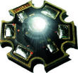 Luxeon LED's available in Red, Green, Blue, White Modules  |
Luxeon LED modules - 350 mA - 80 Lumens. 3.5 to 4.5 VDC What is a Luxeon LED Luxeon Power LED's offer significant advantages over standard Super-bright LEDS. With up to 120 Lumens of Light output, they are very bright having the highest flux in the world. The standard Luxeon White LED will produce 20 lumens per watt which is 5 to 20 time brighter then standard LED's. A standard Luxeon LED will last up to 10 years or 50,000 hours with correct voltage and current supplied to the LED module. Luxeon LEDs are small, directional pinpoints of light which result in highly controllable optical systems with no wasted light. No moving parts, nothing to break, shatter or leak. No UV or Heat is contained in the Light output, but there is heat generated on the back side of the Luxeon LED which will need a heat sink attached for proper performance and longevity of the LED. All Luxeon LEDs are DC voltage operation devices |
||||||
Custom ordered, please allow 2 to 3 weeks for delivery |
|||||||
| LED Light Strips | Hardware Description | ||||||
 - -LED Strips do not come with Power Wires connected, Image shown, illustrates typical power connection that can be easily done. Optional Quick Connectors available.  The LED strips are very flexible  Red LED Strip shown Photo not color correct actual LED's all bright Red |
Each strip operates from 12vdc @170mA per 19" length. Note: The minimum bending radius is 2 cm. The strip may be bent over a smaller radius of the circuit board containing no electronic components and such bends should be made once and fixed in position to avoid cyclic fatigue. Lumen Output :
NOTE: LED Strips do not come with Power Wires connected. |
||||||
|
|||||||
| Luxeon LED Kit Extreme Bright LED |
Hardware Description | ||||||
 Click on Image to view Kit Parts |
If your unsure what to purchase but wish to start learning
about the Luxeon LED modules, then try our Luxeon LED Starter
Kit. |
||||||
|
|||||||
| ELuminescent Experiment Kit |
Hardware Description | ||||||
 |
Made from thin, laminated plastic sheets, this E.L lamp (Electroluminescent
) gives off a neon / fluorescent glow, without generating any
heat or hot spots. Just print your computer-created or hand-drawn
full-color artwork on transparent film or decal paper then apply
to the E.L. lamp and trim to shape, plug in the miniature power
inverter and hit the switch. The effect is awesome! Includes one 1-3/4 inches W x 3-3/4 inches L x .010 inch thick
lamp, six colored overlays, one power inverter with switch, and
12 page instruction manual. |
||||||
|
|||||||
| ELuminescent Effects Kit |
Hardware Description | ||||||
 |
Made from thin, laminated plastic sheets, this E.L lamp gives off a neon / fluorescent glow, without generating any heat. Just apply your full-color artwork transparent film or decal to the E.L.lamp, then using a special power inverter to sequentially light up to six segments of the E.L. lamp with 32 different user-selectable chase patterns. The effect is very awesome! Includes one 1-3/4 inches W x 3-3/4 inches L x .010 inch thick
lamp, six colored overlays, one sequentially power inverter with
32 different user-selectable chase patterns and instruction manual.
|
||||||
|
|||||||
| LED Strobe Stick | Hardware Description | ||||||
 Effects Video |
LED Strobe has 8 - high output 5mm LED's on board, that strobe
ON and OFF Board Size Approx: 3-3/4" L x 1/2" W x 1/2"
H |
||||||
|
|||||||
| Wireless RF 8 Ch Audio MP3 Playback Controller |
Hardware Description | ||||||
 |
Wireless 8 Channel MP3 Audio Playback controller |
||||||
|
|||||||
| Modular 10 Channel - MP3 Audio Playback Controller |
Hardware Description | ||||||
 Main
Control Board Main
Control Board2-1/2" Long 2-3/8" Wide 1/2" High USB-MP3 Module 2-3/4" Long 1-3/4" Wide 7/8" High Operating / Setup Instructions Note: SanDisk USB Drive Recommended HELP: MP3 File Modifications HELP: Flash Drive Formatting |
Newly Enhanced Version Here is a very simple audio controller that when triggered
by pressing the single on-board button or by dry contact closure
at the trigger terminal, will cause the player to play back 1
to 10 MP3 files that are stored on a USB flash device (USB pen
drive not included). These MP3 files can be of any size up to
the capacity of the USB flash device. You can have any number
of files up to 10 on the flash device. Unique setup allows USB-MP3
Module to be mounted in box, cabinet for easy access to USB and
Audio Jack ports. Power Requirements - 9 Vdc @ 0.5 Amp Remote Sensor boards can be
added to trigger the audio playback board automatically, or manual
switch can be used to start playback |
||||||
|
|||||||
| 10-Ch MP3 System with Remote 10-Ch Switch Board |
Hardware Description | ||||||
 MP3 Player Board, VMusic2 Module and 10 Channel Remote Switch Input Board  |
Remote Switch Input Board Newly Enhanced Version An MP3 Stereo Audio Controller, that when triggered by optional
remote relays or manual switches connected to the remote switch
input board will cause the player to play back 1 to 10 MP3 files
that are stored on a USB flash device (USB flash drive not included).
These MP3 files can be of any size up to the capacity of the
USB flash device. You can have any number of files up to 10 on
the flash device. Board operates from 9 VDC @ 0.5 Amp Power Supply.
|
||||||
|
|||||||
| 10 Watt AUDIO AMP - PRO | Hardware
Description....... |
||||||
 Small Board Size: 31/2" L x 2" W x 1-1/4" H Board is pre-assembled and tested. Application Notes Setup Examples |
10 Watt Class D Stereo Audio Amplifier. Power your own speakers directly with this very efficient
stereo power amplifier. All connections are made using screw
closure terminal strips to allow for simple and direct wiring
of speakers and supplying power. Volume is adjustable using the
handy on-board potentiometer with turn knob to allow for precise
control of volume. The audio source input is supplied simply
by taking an audio patch cable and connecting the AMP Pro to
a playback device such as any of the Blue Point Engineering MP3
Playback Control Boards. |
||||||
|
|||||||
| R/C Servo Controlled 4-Ch Video Switcher |
Hardware Description | ||||||||||||
|
|
Unique servo signal controlled electronic video switching
system which provides clean and fast switching between 4 video
channels to 1 channel. The Video switcher board will switch one of four video input
signals to a buffered video output line. The Video Switcher board
is suitable for all standard CCTV type video signals. System is excellent for operating 4 different cameras, and
sending video signal from one of the 4 cameras out to a remote
transmitter. Put full 360 degree vision on your robot, airplane,
animatronic character, or setup a covert operation with remote
control. |
||||||||||||
|
|||||||||||||
| LASER Target GAME System | Item Description | ||||||
 Main Board Size: 4-7/8" L x 3-3/8" W x 1" H Remote LED Board Size: (not shown) 1-71/4" L x 3-3/8" W x 7/8" H CDS Cell Sensor Board: 1-1/8" L x 1" W x 7/8" H LASER Caution Note |
This project will detect "hits" from a LASER beam
on a remotely mounted target board and display the hit count
on a large LED display. When hits are detected, the display will
count down or up and trigger a beeper, 2 large LEDs (one located
on the Main Board and the other located on the remote board)
and SSR #1 for 3 seconds. When the hit count gets to 0 the large
LEDs will rapidly flash, the beeper will annunciate continuously
and SSR #2 will actuate. This will continue until the reset button
is pressed (a remote terminal is available), or if the Auto/Manual
switch is set to Auto, the board will automatically reset after
a user-defined time interval. The user can set the hit count
starting value (1 100) and the reset time (1-20 seconds)
. The target boards are attached by a 6 foot ribbon cable. The
target sensitivity can be adjusted by an on-board potentiometer
to allow optimum response in different lighting conditions. The
beeper can be silenced with an adjacent slide switch. (Power supply, LASER, not included) |
||||||
|
|||||||
| LASER Target Relay | Item Description | ||||||
 Main Board Size: 2-1/4" L x 2-1/4" W x 7/8" H Remote LED Board Size: (not shown) 1-71/4" L x 3-3/8" W x 7/8" H CDS Cell Sensor Board: 1-1/8" L x 1" W x 7/8" H LASER Caution Note |
This board will detect "hits" from a LASER on a
remotely mounted target. When hits are detected, 2 large LEDs
(one located on the Main Board and the other located on the remote
sensor board) and both SSRs will be activated ON for 3 seconds.
The target board is attached by a 6 foot ribbon cable. The target
sensitivity can be adjusted by an on-board potentiometer to allow
optimum response in different lighting conditions. Board wil
automatically reset waiting for next LASER hit. (Power supply, LASER, not included)
|
||||||
|
|||||||
| Ground Station Tracking System | R/C Servo Control Fluid Pump |
| R/C Servo Control Air Pump | Rescue POD Drop Mechanism |
| Tennis Ball Drop Mechanism | Sensor POD Drop System |
| Ping Pong Ball Drop Mechanism | Hexacopter Winch System |
| Duo LASER R/C Tracking Mechanism | Video Drop POD System |
| Camera Pan and Tilt Mechanism | R/C Servo Pneumatic Valve |
| Servo Controlled Drop Mechanism | |
| Mini Fluid Pump | Hardware Description | |||||||||
 Pump Instructions  |
Small 12 Volt DC powered pump for moving fluids. 12 Vdc operated electric pump Pump comes with connection tubing, electrical hook up wire,
tube adapter, plastic tube "T" Power supply not included. |
|||||||||
|
||||||||||
| R/C Servo Pneumatic Valve | Product Information | ||||||
 Board Size: 3-7/8" L x 2-5/8" W x 1-3/8" H |
.......New Design - R/C Servo Pneumatic Valve Unique R/C servo operated - Single-Acting 3-way valve. Runs directly from R/C receiver, Wizard, or Puppet boards, no interface, linkage or servo needed. Valve activation point ON and OFF default can be set. This valve can also be used to operate larger pilot-operated valves, Props, Robot modules, or any where you need programmable air control. PC board can be split with the valve at a different location than the controller electronics. Board Size. 3-7/8" L x 2-5/8" W x 1-3/8" H (12 Vdc power supply, R/C receiver, Wizard Puppet controllers, servo wire lead not included ) |
||||||
Custom Order, Please Contact Blue Point Engineering for Details |
|||||||
| Mini Air Pump - 50 | Hardware Description | ||||||
 Click on Image for Closeup Views Pump Size: Length: 5-3/4" Width: 1-1/2" Height: 3-1/2" Mini Air Pump Power Driver Board  Mini Air Pump with Optional R/C Servo Control Board |
12Vdc operated Mini Air Pump. (Hose, gauge, clamp, Air tank, power supply not included)
Mini Air Pump R/C Power Driver Board (VDC output power supply not included) ......... Mini Air Pump Power Driver Board |
||||||
Custom Order, Please Contact Blue Point Engineering for Details |
|||||||
| R/C Servo Controlled Tennis Ball Drop Mechanism |
Product Information | ||||||
- |
.......R/C Servo Controlled Tennis Ball Drop Mechanism Unique R/C servo operated - |
||||||
Custom Order, Please Contact Blue Point Engineering for Details |
|||||||
| R/C Servo Controlled Ping Pong Ball Drop Mechanism |
Product Information | ||||||
- |
.......R/C Servo Controlled Tennis Ball Drop Mechanism Unique R/C servo operated - |
||||||
Custom Order, Please Contact Blue Point Engineering for Details |
|||||||
| R/C Servo Controlled Universal Drop Mechanism |
Product Information | ||||||||||||
IMAGES  |
.......R/C Servo Controlled Universal Drop Mechanism Unique R/C servo operated mechanism designed to hold payload on UAV and drop it under command from a servo and remote RF transmitter signal Module is constructed from machined aluminum with attached
pull pin setup assembly attached to servo arm.. When R/C servomotor
is activated will pull back release pin holding payload. Mounting
holes on drop mechanism makes mounting easy. |
||||||||||||
|
|||||||||||||
| R/C Servo Controlled Winch System |
Product Information | ||||||
- |
.......R/C Servo Controlled Winch System Unique R/C servo operated - |
||||||
Custom Order, Please Contact Blue Point Engineering for Details |
|||||||